Table of Contents
GL.iNet GL-X3000
GL.iNet GL-X3000 is a dual core 1.3GHz WiFi-6 router based on Mediatek MT7981A SoC with Quectel RM520N 5G (Sub-6 GHz) modem module.
GL.iNet GL-XE3000 is the same device as the GL-X3000 except for an additional battery.

Supported Versions
Hardware Highlights
Installation
Installing / Upgrading OpenWrt firmware
Upgrading the firmware from Stock U-Boot Web-UI
 This easy way works ONLY if you are running the stock bootloader delivered by GL iNet.
If you are failing to enter the U-Boot Web-UI (as described below) you might have flashed another version of the bootloader that supports TFTP upload only. In that case, you need to follow the TFTP flashing process.
This easy way works ONLY if you are running the stock bootloader delivered by GL iNet.
If you are failing to enter the U-Boot Web-UI (as described below) you might have flashed another version of the bootloader that supports TFTP upload only. In that case, you need to follow the TFTP flashing process.
For the GL.iNet GL-X3000, currently installation & upgrading the firmware must be performed within U-Boot bootloader. Depending on which U-Boot you have installed, you can either use the Web-UI or TFTP. Web-UI is possible as long as you run the stock U-Boot that is shipped with the device. See also GL.iNET Debrick documentation for more detail.
Follow below procedure to access Web-UI:
- Download the desired firmware
glinet_gl-x3000-squashfs-sysupgrade.bin - Remove the power of router. Connect your computer to the Ethernet port (either LAN or WAN) of the router. You MUST leave all the other ports unconnected.
- Press and hold the Reset button firmly, and then power up the router by plugging in the power.
- Then you will see a the LAN LED flashes 5 times then WIFI LED stays on. Please release your finger after that sequence.
- Manually configure static IP address on your computer as 192.168.1.2 with gateway 192.168.1.1 & subnet mask 255.255.255.0
- Use browser to visit http://192.168.1.1/
- You can see the “FIRMWARE UPDATE” Web UI as shown here:
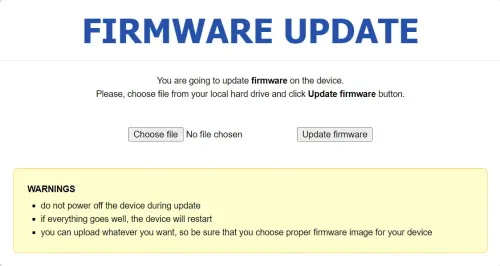
- Click
Choose filebutton to locate the OpenWrt sysupgrade firmware file. Then clickUpdate firmwarebutton. - Wait for around 3 minutes. Don’t power off your device when updating. The router is ready when both power and Wi-Fi LED are on.
- Access the Luci UI (if non-snapshot) and login

Upgrading or Changing U-boot bootloader (Optional)
Flash and Upgrade Stock U-Boot (Optional)
IMPORTANT NOTICE:
Upgrading or changing U-Boot is a risky operation and incorrect operation could brick your router!
Please make sure to backup your current stock U-Boot before proceeding to upgrade or change it.
A. Backup your GL.iNET Stock U-boot
To do so, SSH to the device and copy the content of mmcblk0p4 to a file.
dd if=/dev/mmcblk0p4 of=/tmp/X3000_uboot_fip_stock.bin
Download this file to your client PC and store it in a safe place.
To check which U-Boot version you have on your device, you can run
strings /dev/mtd0 | grep U-Boot in the terminal.
B. Upgrade your GL.iNET Stock U-boot version
If you want to update / change the U-Boot Version you can use the WEB UI to upload a new version.
It is similar to the U-Boot Web-UI flashing procedure with some minor difference: See also GL.iNET Upgrade Uboot version documentation for more detail.
- Download the desired uboot
glinet_gl-x3000-bl31-uboot.fip - Remove the power of router. Connect your computer to the Ethernet port (either LAN or WAN) of the router. You MUST leave all the other ports unconnected.
- Press and hold the Reset button firmly, and then power up the router by plugging in the power.
- Then you will see a the LAN LED flashes 5 times then WIFI LED stays on. Please release your finger after that sequence.
- Manually configure static IP address on your computer as 192.168.1.2 with gateway 192.168.1.1 & subnet mask 255.255.255.0
- Use browser to visit http://192.168.1.1/uboot.html
- You can see the “U-BOOT UPDATE” Web UI as shown here:

- Click
Choose filebutton to locate the GL.iNET U-boot FIP file. Then clickUpdate U-bootfirmware button. - Wait for around 3 minutes. Don’t power off your device when updating. The router is ready when both power and Wi-Fi LED are on.
- Access the Luci UI (if you've flashed OpenWrt already) and login

Alternatively: Replace Stock U-boot with OpenWrt U-boot (Optional)
Alternatively, from a root shell on the running system, unlock the boot partition with
echo 0 >/sys/block/mmcblk0boot0/force_ro
then write
| openwrt-mediatek-filogic-glinet_gl-x3000-bl31-uboot.fip | to | FILL-IN |
|---|---|---|
| openwrt-mediatek-filogic-glinet_gl-x3000-bl31-uboot.fip to | to | /dev/mmcblk0p4 |
| openwrt-mediatek-filogic-glinet_gl-x3000-preloader.bin | to | /dev/mmcblk0boot0. |
OEM installation using the TFTP method
If you are unable to reach the U-Boot Web-UI, as described above, you might have another version (generic OpenWRT?) of U-Boot installed. → generic.flashing.tftp
Specific values needed for tftp
 Enter values for “FILL-IN” below
| Bootloader tftp server IPv4 address | FILL-IN |
|---|---|
| Bootloader MAC address (special) | FILL-IN |
| Firmware tftp image | Latest OpenWrt release (NOTE: Name must contain “tftp”) |
| TFTP transfer window | FILL-IN seconds |
| TFTP window start | approximately FILL-IN seconds after power on |
| TFTP client required IP address | FILL-IN |
Upgrading OpenWrt
For GL-X3000, the regular Luci or CLI based sysupgrade method is NOT working for some reason.
You need to follow the process as described above in Upgrading the firmware from Stock U-boot Web-UI.
Flash layout
Find out flash layout, then add the flash layout table here (copy, paste, modify the example).
Please check out the article Flash layout. It contains examples and explanations that describe how to document the flash layout.
Setup 5G connectivity
Setting up modem for 5G
Prerequisite: You followed the MBIM / QMI setup described here
By default, the modem is shipped with a setting that the modem communicates via PCIe.
1) Change this to let it communicate via USB.
2) set MBIM mode (not the proprietary qmi)
3) Check if mbim mode is set
Install terminal emulation program e.g. picocom:
opkg install picocom
Start the connection with
picocom /dev/ttyUSB2
Enter AT to see if the modem responses with “OK”
1) Change this to let it communicate via USB.
Then, check the current setting:
AT+QCFG="data_interface"
If the response shows something with 1,0 then the modem communicates over PCIe and you need to do the changes accordingly:
AT+QCFG="data_interface",0,0
Reboot and check if there is a device /dev/cdc-wdm0
2) set MBIM mode (not the proprietary qmi)
Same as above, start the pico com session on ttyUSB2
AT+QCFG="usbnet",2
To confirm your changes, reboot the device or send
AT+CFUN=1,1
command.
3) Check if mbim mode is set
1) ssh to the router
2) cat /sys/kernel/debug/usb/devices
Check the output should be similar to:
T:  Bus=01 Lev=02 Prnt=02 Port=01 Cnt=02 Dev#=  4 Spd=480  MxCh= 0
D:  Ver= 2.10 Cls=00(>ifc ) Sub=00 Prot=00 MxPS=64 #Cfgs=  1
P:  Vendor=2c7c ProdID=0801 Rev= 5.04
S:  Manufacturer=Quectel
S:  Product=RM520N-GL
S:  SerialNumber=aae44c2
C:* #Ifs= 5 Cfg#= 1 Atr=a0 MxPwr=500mA
I:* If#= 0 Alt= 0 #EPs= 2 Cls=ff(vend.) Sub=ff Prot=30 Driver=option
E:  Ad=01(O) Atr=02(Bulk) MxPS= 512 Ivl=0ms
E:  Ad=81(I) Atr=02(Bulk) MxPS= 512 Ivl=0ms
I:* If#= 1 Alt= 0 #EPs= 3 Cls=ff(vend.) Sub=00 Prot=40 Driver=option
E:  Ad=83(I) Atr=03(Int.) MxPS=  10 Ivl=32ms
E:  Ad=82(I) Atr=02(Bulk) MxPS= 512 Ivl=0ms
E:  Ad=02(O) Atr=02(Bulk) MxPS= 512 Ivl=0ms
I:* If#= 2 Alt= 0 #EPs= 3 Cls=ff(vend.) Sub=00 Prot=00 Driver=option
E:  Ad=85(I) Atr=03(Int.) MxPS=  10 Ivl=32ms
E:  Ad=84(I) Atr=02(Bulk) MxPS= 512 Ivl=0ms
E:  Ad=03(O) Atr=02(Bulk) MxPS= 512 Ivl=0ms
I:* If#= 3 Alt= 0 #EPs= 3 Cls=ff(vend.) Sub=00 Prot=00 Driver=option
E:  Ad=87(I) Atr=03(Int.) MxPS=  10 Ivl=32ms
E:  Ad=86(I) Atr=02(Bulk) MxPS= 512 Ivl=0ms
E:  Ad=04(O) Atr=02(Bulk) MxPS= 512 Ivl=0ms
I:* If#= 4 Alt= 0 #EPs= 3 Cls=ff(vend.) Sub=ff Prot=ff Driver=qmi_wwan
E:  Ad=88(I) Atr=03(Int.) MxPS=   8 Ivl=32ms
E:  Ad=8e(I) Atr=02(Bulk) MxPS= 512 Ivl=0ms
E:  Ad=0f(O) Atr=02(Bulk) MxPS= 512 Ivl=0ms
After that, follow the guide ltedongle and install all packages required for MBIM
Debricking
Booting into the uBoot UI should always be possible.
If you have managed to break the boot loader (wrong dd) you can try this: https://forum.openwrt.org/t/ax3000t-bricked/198448
Basic configuration
→ Basic configuration After flashing, proceed with this.
Set up your Internet connection, configure wireless, configure USB port, etc.
Specific Configuration
Bridge mode
Follow the guide https://forum.gl-inet.com/t/gl-x3000-bridge-mode-wan-ip-passthrough/32715/10 to set the router to bridge mode.
Please note! This seems to be beta / experimental and without any warranty.
SSH to the device and execute
curl -k http://127.0.0.1/rpc -H 'glinet: 1' -d '{"jsonrpc":"2.0","method":"call","params":["","netmode","set_mode",{"mode":"passthrough","mask":"auto"}],"id":1}'
Switch Ports (for VLANs)
Please fill in real values for this device, then remove the EXAMPLEs
Numbers 0-3 are Ports 1-4 as labeled on the unit, number 4 is the Internet (WAN) on the unit, 5 is the internal connection to the router itself. Don't be fooled: Port 1 on the unit is number 3 when configuring VLANs. vlan0 = eth0.0, vlan1 = eth0.1 and so on.
| Port | Switch port |
|---|---|
| Internet (WAN) | EXAMPLE 4 |
| LAN 1 | EXAMPLE 3 |
| LAN 2 | EXAMPLE 2 |
| LAN 3 | EXAMPLE 1 |
| LAN 4 | EXAMPLE 0 |
Hardware
Info
- This table is automatically generated, once the correct filters for Brand and Model are set.
- If you see “Nothing.” instead of a table, please edit this section and adjust the filters with the proper Brand and Model. Just try, it's easy.
- If you still don't see a table here, or a table filled with '¿': Is there already a Techdata page available for GL.iNet GL-X3000 ? If not: Create one.
- If you see a table with the desired device data, everything is OK and you can delete this text and the
<WRAP>that encloses it. - If it still doesn't work: Don't panic, calm down, take a deep breath and contact a wiki admin (tmomas) for help.
---- datatemplatelist dttpllist ---- template: meta:template_datatemplatelist cols : Brand, Model, Versions, Device Type, Availability, Supported Since Commit_git, Supported since Rel, Supported current Rel, Unsupported, Bootloader, CPU, Target, CPU MHz, Flash MBs, RAM MB, Switch, Ethernet 100M ports_, Ethernet Gbit ports_, Comments network ports_, Modem, VLAN, WLAN 2.4GHz, WLAN 5.0GHz, WLAN Hardwares, WLAN Comments_, Detachable Antennas_, USB ports_, SATA ports_, Comments USB SATA ports_, Serial, JTAG, LED count, Button count, Power supply, Device Techdata_pageid, Forum topic URL_url, wikidevi URL_url, OEM Device Homepage URL_url, Firmware OEM Stock URL_url, Firmware OpenWrt Install URL_url, Firmware OpenWrt Upgrade URL_url, Comments_ filter : Brand=GL.iNet filter : Model=GL-X3000 filter : Versions=
Photos
Front:
Insert photo of front of the casing
Back:
Insert photo of back of the casing
Backside label:
Insert photo of backside label
Opening the case
→ Warranty
Describe what needs to be done to open the device, e.g. remove rubber feet, adhesive labels, screws, ...
- To remove the cover and open the device, do a/b/c
Main PCB:
Insert photo of PCB
Serial
→ port.serial general information about the serial port, serial port cable, etc.
How to connect to the Serial Port of this specific device:
Insert photo of PCB with markings for serial port
Replace EXAMPLE by real values.
| Serial connection parameters for GL.iNet GL-X3000 @@Version@@ | EXAMPLE 115200, 8N1, 3.3V |
|---|
JTAG
→ port.jtag general information about the JTAG port, JTAG cable, etc.
How to connect to the JTAG Port of this specific device:
Insert photo of PCB with markings for JTAG port
Bootloader mods
Hardware mods
None so far.
Bootlogs
OEM bootlog
COPY HERE THE BOOTLOG WITH THE ORIGINAL FIRMWARE
OpenWrt bootlog
COPY HERE THE BOOTLOG ONCE OPENWRT IS INSTALLED AND RUNNING
Notes
Space for additional notes, links to forum threads or other resources.
GL.iNET official documentation
- Upgrade GL.iNET firmware version via Debrick process - This process is currently required for GL-X3000 to install and upgrade official OpenWrt images
- Upgrade U-boot booloader version (Optional) - Exercise caution because corrupting U-boot partition could brick your router!